Holes
This group adds two extra machining operations: handle holes in the fronts and holes for drawer runners (runner slides). The generated holes appear in the machining/hardware list and — when holes are shown — in the 3D model.
Handle holes
Where and how handles are drilled in doors and drawer fronts:
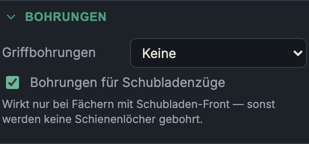
None
- What it does: No handle hole.
- When to use it: Handleless fronts (push-to-open, handle rails, routed grips).
- Pros & cons: Smooth front; the opening mechanism must be solved another way.
Single (centered)
- What it does: A single, centered hole.
- When to use it: Knobs or single-hole handles.
- Pros & cons: Minimal drilling effort; only for handles fixed at a single point.
Handle pair (bar)
- What it does: Two holes at the hole spacing for a bar/pull handle.
- When to use it: The usual bar-handle mounting.
- Pros & cons: Stable two-point fixing; the hole spacing must match the handle you bought.
Handle hole parameters
- Hole spacing (only for "Handle pair (bar)", 32–320 mm, default 128 mm): the hole spacing of the bar handle — common sizes are 96/128/160 mm.
- Hole Ø (3–12 mm, default 5 mm): drill diameter for the handle screw.
- Edge offset (10–150 mm, default 40 mm): distance from the relevant front edge — for drawers from the top edge, for doors from the opening/vertical edge.
Holes for drawer runners
Switch that generates the mounting holes of the runner slides on the carcass walls (and vertical dividers) of the drawer compartments.
You choose the runner system and length at the drawer — in the group Front → Drawers. There, the product also decides on the drawer box (wooden box or metal drawer side). Here you only switch on the drilling of the runner holes and see the hole pattern.
- What it does: Drills the runner hole pattern into the walls of each drawer compartment — outer side and vertical divider/partition — and, with side mounting, additionally into the drawer sides. A compartment without drawers is left free.
- When to use it: For production (CNC) or for marking out.
Hole pattern display
Below the selection the generated hole pattern is shown, e.g. "Hole pattern: 37, 69, 320 mm from front edge · height −14.6 mm from drawer bottom": the hole positions from the front edge and the height of the runner line above the drawer bottom (negative = below, typical for undermount). Possible additional notes:
- Rear support via separate bracket — no side hole at the rear; the rear retention sits on a depth-dependent bracket.
- Dimensions from manufacturer drawing — hole pattern read from a drawing (not from a CNC template); check against the data sheet before production.
Custom (dimensions)
If Custom (dimensions) is chosen as the system at the drawer, the manual hole pattern fields appear here (treated as side mounting, the drawer side is drilled too):
- Front holes per runner: number of front fixing holes.
- First hole from front: distance of the first hole from the front edge.
- Hole spacing: grid spacing of the front holes (32 mm system).
- Height from drawer bottom: height of the runner line (negative = below the drawer bottom).
- Runner length (0 = auto): nominal length; a hole is set at the rear at this length, 0 = automatic from the depth.
Next: Plinth & worktop