Fittings & drilling
This group gathers — per cabinet — the front- and drawer-related fittings with the drilling they need: concealed (cup) hinges and handles in the fronts, plus the drawer runners (runner system + runner holes). The resulting holes appear in the parts/hardware list and — when holes are shown — in the 3D model.
Concealed (cup) hinges
Only for a doors front. Sets where the hinges sit — and hence which way the door opens: the door opens on the edge opposite the hinge side.
- Hinge side: Which vertical edge the concealed hinges (and their cup holes) sit on — Automatic (outer) (left door on the left, right door on the right; a single door on the left), or fixed Left/Right.
- Automatic count: The number of hinges follows the door height (2 hinges up to 900 mm, then +1 per ~700 mm). This mirrors the hardware rule of thumb.
- Cup Ø (20–40 mm, default 35 mm): diameter of the cup hole (a standard concealed hinge = 35 mm).
- Cup centre from door edge (16–30 mm, default 22 mm): distance of the cup centre from the door edge.
- Edge distance of outer hinges (40–150 mm, default 90 mm): distance of the topmost/bottommost hinges from the door ends.
Handles
Where and how handles are drilled in doors and drawer fronts:
None
- What it does: No handle bore.
- When to use it: Handleless fronts (push-to-open, handle rails, machined grips).
- Pros & cons: Clean front; the opening mechanism has to be solved another way.
Single (centred)
- What it does: One single, centred bore.
- When to use it: Knobs or single-fix pulls.
- Pros & cons: Minimal drilling; only for handles fixed at one point.
Bar handle (2 holes)
- What it does: One bar/bow handle fixed at two holes, hole spacing apart (not a pair of handles — it's a single handle with two bores).
- When to use it: The usual bar-handle mounting.
- Pros & cons: Solid two-point fixing; the hole spacing must match the handle you buy.
Orientation
- Automatic: doors get a vertical handle on the opening edge, drawers a horizontal one near the top edge — the usual choice.
- Vertical / Horizontal: forces the orientation — e.g. a horizontal bar handle on a door (the pair then runs across, centred near the top edge).
Handle bore parameters
- Hole spacing (bar handle only, 32–320 mm, default 128 mm): the bore spacing of the bar handle — common sizes are 96/128/160 mm.
- Hole Ø (3–12 mm, default 5 mm): drill diameter for the handle screw.
- Edge offset (10–150 mm, default 40 mm): distance from the relevant front edge — horizontal from the top edge, vertical from the opening/vertical edge.
- Reference edge & distance / offset: the position along the handle. Shown once a fixed orientation is chosen (with Automatic it stays centred). Pick the reference edge — vertical Top/Centre/ Bottom, horizontal Left/Centre/Right. For Top/Bottom (or Left/Right) you give the distance from that edge. For Centre you enter the offset from the middle (field Offset, 0 = centred): a positive value shifts up (or left), a negative one (typed with −) shifts down (or right). The direction is shown after the value — (up), (down) … or (centred) at 0. So a door handle can sit flush near the top instead of dead-centre.
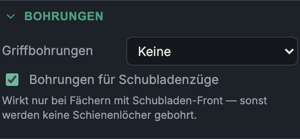
Drawer runners
This section only appears when the cabinet contains at least one drawer compartment.
Runner system & runner length
Here you pick the runner system (a catalogue system like Blum Legrabox/Metabox … or Custom) and the runner length. The system also defines the drawer box: a metal-sided system supplies the sides (only the bottom + back are then cut for the drawer), while a wooden system leaves the wood-box options with the drawer. The length is bounded by the cabinet depth; 0 = automatic from the depth.
Drill runner holes
A switch that creates the runner mounting holes on the cabinet sides (and dividers) of every drawer compartment — plus, for side-mount runners, on the drawer sides. Off = no runner holes (e.g. if you mark them out yourself).
Drill-pattern readout
Below the switch, the generated pattern is shown, e.g. "Pattern: 37, 69, 320 mm from the front edge · height −14.6 mm from the drawer bottom": the hole depths from the front edge and the height of the runner line above the drawer bottom (negative = below it, typical for under-mount). Possible extra notes:
- Rear support via a separate bracket — no side hole at the rear; the rear stay sits on a depth-dependent bracket.
- Dimensions from a manufacturer drawing — pattern read from a drawing (not a CNC template); cross-check with the datasheet before machining.
Custom
With Custom selected as the system, the manual pattern fields appear (treated as side-mount, the drawer side is drilled too):
- Front holes per runner: number of front fixing holes.
- First hole from front: distance of the first hole from the front edge.
- Hole spacing: grid spacing of the front holes (32 mm system).
- Height from drawer bottom: height of the runner line (negative = below the drawer bottom).
- Runner length (0 = auto): nominal length; a rear hole is placed at this length, 0 = automatic from the depth.
Next: Plinth & Worktop