Lists, Cut List & Sawing Plan
The bottom bar brings together all generated lists. It has four tabs: Parts list, Costs, Cut list and Drawing. The bar can be resized in height and collapsed (more room for the 3D view).
Parts list
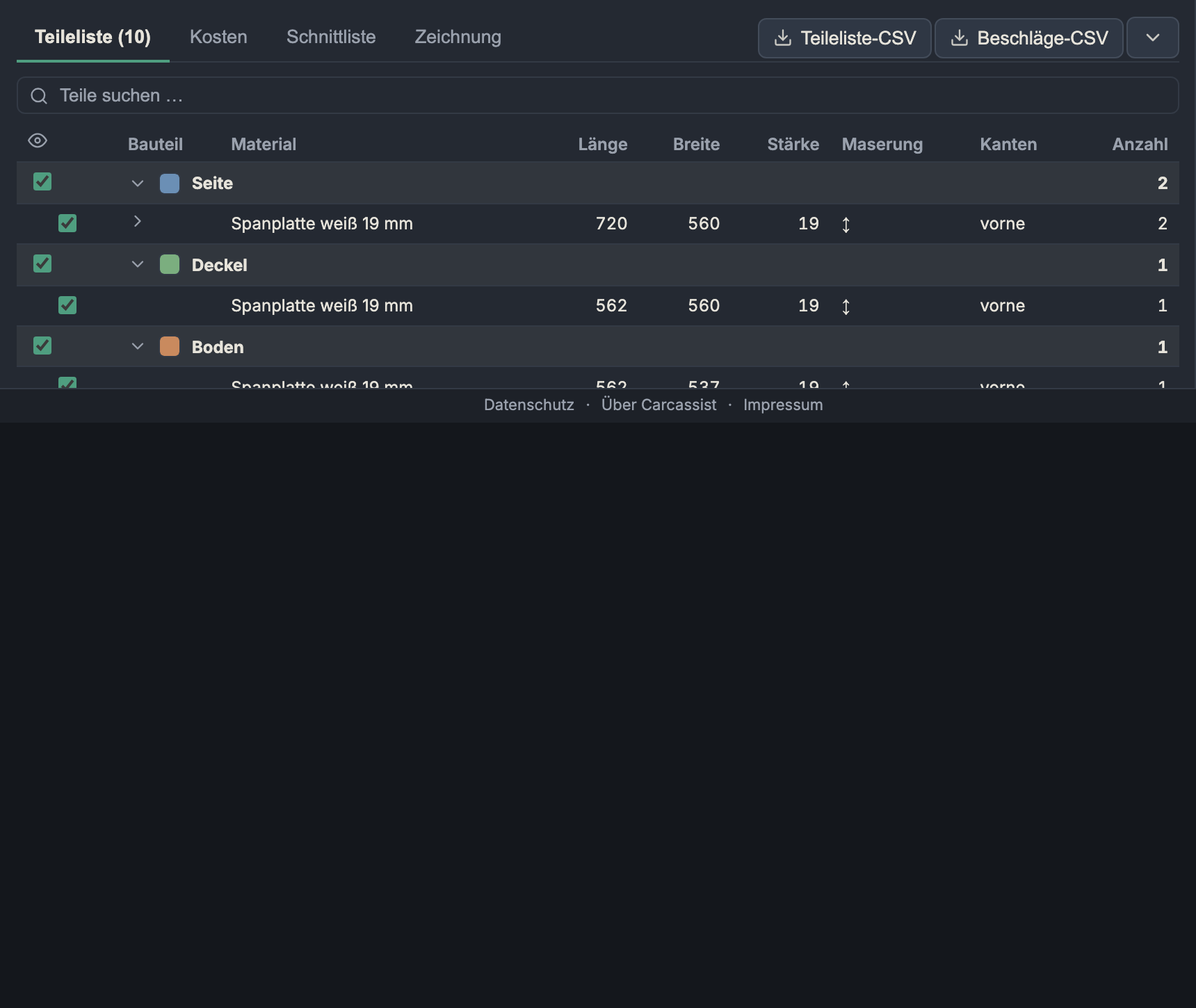
The bill of materials for all cut parts, grouped hierarchically.
- Grouping: by default by role (side, bottom, top panel, back panel, door, drawer front …). With several carcasses you can switch to by carcass (then carcass first, roles within it).
- Columns: part, material, length, width, thickness, grain (↕ lengthwise, ↔ crosswise, – don't care), edges (which edges are edge-banded) and quantity. Identical formats are combined into a single row (with a count); use the arrow to expand the individual parts.
- Search: free-text search over name, material, dimensions and individual-part labels (e.g. "Drawer 2" finds the second drawer).
- Visibility (eye column): Every row/group can be shown and hidden — this hides the parts in sync in 3D (handy for looking inside). The app counts hidden parts in the 3D overlay; "show all" resets.
- Colour swatch: Pick a colour per role — the same colour is used by the 3D option Colourise.
Hardware & machining
Below the parts list are two further tables (where applicable):
- Hardware = purchasable parts, one row per specification: dowel Ø…, Domino …, biscuit #…, screws, concealed hinges, shelf supports. This lets you order the hardware directly.
- Machining = machining steps (not hardware): System 32 holes, grooves, box joints. (A groove is deliberately not hardware.)
CSV export: Parts-list CSV and Hardware CSV via the buttons at top right.
Costs
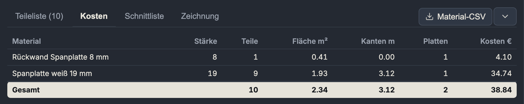
One row per material: thickness, parts, area m², edges m (running metres of edge banding), sheets (estimated number of sheets) and costs € (area × €/m² of the material, where entered). A total row closes it off. CSV export: Material CSV.
The sheet count/costs here are a quick estimate; the real, optimised sheet requirement is delivered by the cut list.
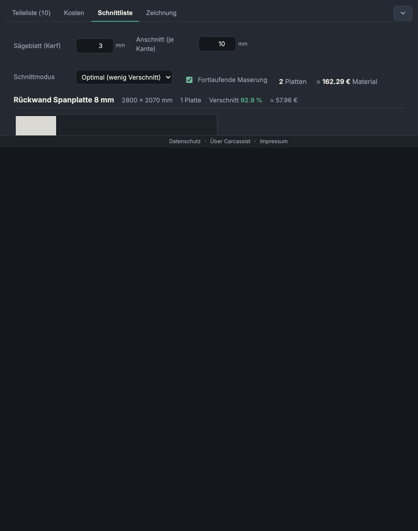
Cut list (sawing plan / nesting)

Here all parts are nested onto real sheet formats, separately per material. Each sheet is drawn to scale, with a part label, dimensions and (where there is grain) grain stripes. The controls are at the top:
Saw blade (kerf)
The kerf width of the saw blade (0–10 mm, step 0.1; project default 3 mm). Between two parts this width is lost per cut. The app only accounts for the kerf on cuts between parts — a single part may take up the full usable area.
Trim (per edge)
A clean trimming margin reserved on every side of the sheet (0–50 mm, default 10 mm) before nesting. Usable area = sheet dimension − 2 × trim per axis. Industrial sheets often have an untidy/chipped factory edge — the trim saws it off.
Cutting mode
- Optimal (low waste): A best-of-N optimisation
tries many variants (orderings × orientation × placement heuristic ×
rotate on/off) and keeps the cleanest one. All layouts remain guillotine-
cuttable (continuous edge-to-edge cuts, as a panel/table/plunge saw can
actually perform — interlocking "pinwheel" layouts can't be sawn).
- Pros & cons: best sheet yield, good looks; the cutting pattern is less uniform than with strip cutting.
- Strips (rip): The production method — first rip strips
across the full sheet length, then cross-cut the parts to length from each
strip. Only works if every part fits into a strip; otherwise the app
automatically falls back to the free nest.
- Pros & cons: markedly fewer rip cuts at the panel saw, a cleaner workflow, the leftover pieces are whole strips; tends to produce slightly more waste than "Optimal".
- Strip width (0–2070 mm): forces every strip to this exact width (e.g. the carcass depth as a standard rip). 0/empty = usual/part-based widths.
Continuous grain
- What it does: Cuts the front stack of a carcass as one panel and then rips it apart — so the grain runs continuously across all fronts (drawer fronts/doors).
- When to use it: With solid wood/décor with visible grain, when the fronts should look "from one piece".
- Pros & cons: Elegant continuous grain flow; in the plan the combined panel is framed with a dashed outline, the internal kerf gaps are the ripping cuts. It ties the fronts together by position (a little less freedom when nesting). Only has an effect on materials with grain.
Grain display
Parts on a material with grain are drawn with grain stripes and never rotated (the running direction is preserved). Since they are not rotated, the stripes always run along the sheet length. A dashed brown outline marks a continuous-grain panel.
Waste & offcut compaction
- Waste % per material:
1 − part area / sheet area. - After nesting the app compacts each sheet: the parts are "pushed together" towards the top/left, so the remainder ends up in one contiguous offcut rather than in slivers on both sides — the leftover piece is thus preserved as a usable offcut sheet. Compaction never changes the sheet count or the waste, and only happens if the result stays overlap-free and guillotine-cuttable.
- The optimisation rates layouts in this order: (1) sheet count (the real material consumption), (2) empty area on the non-last sheets (gathers the waste on the last sheet into one large remainder), (3) number of distinct cut edges as a pure tiebreaker (cleanliness).
Strip cutting
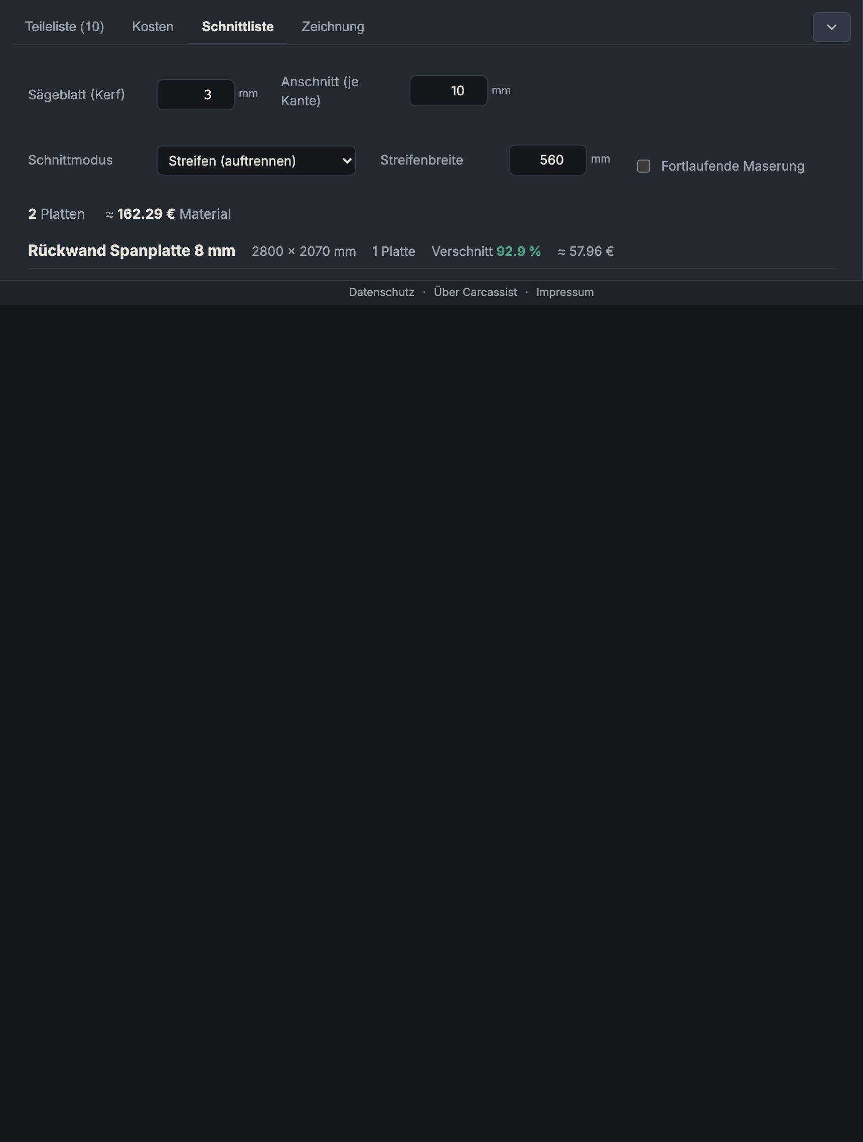
In strip mode the parts lie in full lengthwise strips — visible from the continuous rip bands.
Sawing plan & cut preview
- Sawing plan — N cuts: Under each sheet an ordered cut list expands: per cut the direction (horizontal/vertical), position in mm and the range it runs over. Horizontal cuts (rows/strips) come first.
- Cut preview: A button opens an interactive preview — click a piece to see the next cuts on it (step by step to the finished part).
- Unplaceable parts: Parts that don't fit on any sheet of this size (too large) are listed with a warning and dimensions instead of being silently dropped.
Drawing

Scaled technical drawings: an overview/cover page (overall dimensions, carcasses, sheets, parts, positions) and scaled individual-part drawings with dimensioning, grain direction, drilling patterns (grid, first hole, rows) and depths. Export: Print / PDF (multi-page, not clipped to the first page) and DXF (CAM) for further processing.
Next: 3D view